Startup Bug with the Xilinx SRL16
Issue
As you may know XST typically
synthesizes shift register constructs
(without a reset) into a
SRL16E component. The SRL16E behaves
well unless you’re using
initial signal values that start shifting during
GSR. The initial pattern gets distorted and causes the
design to fail.
Synplify currently does not
implement initial values into SRL16 and will
not correctly implement this design.
A search of the internet to
find a solution to this problem found a
number of similar issues but
no definitive resolution.
Design Description
This design will create a
fixed pattern running at 50 Mbits per second.
It utilizes a shift register
of 8 bits in length that is initialized to a x”88”
starting value.
The code for this design is:
library
ieee; use ieee.std_logic_1164.all;
entity
srl16e_bug is port (
clk
: in std_logic;
lsb_out
: out std_logic);
end entity
srl16e_bug;
architecture
rtl of srl16e_bug is
signal byte_internal : std_logic_vector(7
downto 0) := x"88";
begin
shift_right : process begin
wait until rising_edge(clk);
byte_internal<= byte_internal(0) &
byte_internal(7 downto 1);
end process shift_right;
lsb_out <= byte_internal(0);
end
architecture rtl;
Code
Sample 1 Fixed Pattern Shift Register
An RTL simulation of this
code shows the proper operation with the
“88” being
rotated through the SLR16E. The TestBench simply
supplies a clock. This operation is shown in Figure 1. This shows
the
output pulsing high every 4 clock cycles.

Figure
1 RTL Simulation
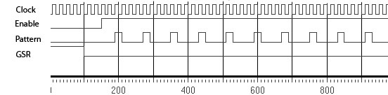
Implemented in the FPGA
The next step is to compile
this design using the Xilinx ISE Webpack
tool. Version 10.1.03 is utilized in this example.
Route simulation model is
then simulated. The results of this simulation
(Figure 2) show a discrepancy.
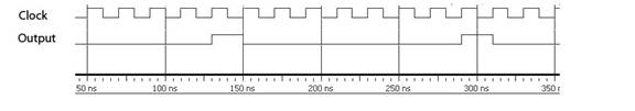
Figure
2 Post PAR Simulation
The output is only pulsing
high every 8th clock. The
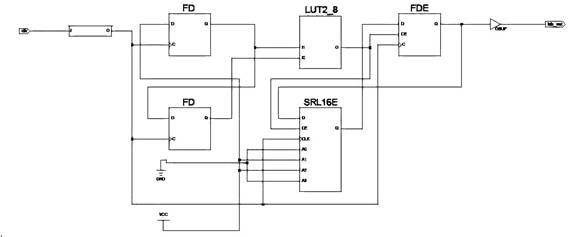
Technology view
(Figure 3) shows the implementation of this circuit that XST
produced.
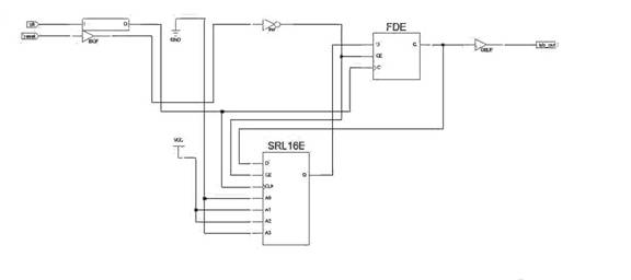
Figure
3 Technology view of circular shift function
XST implemented 7 bits of the
shift register in the SRL16E and the
remaining bit is implemented in the FDE.
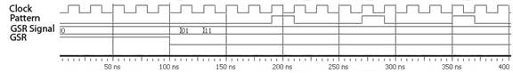
The
simulation in Figure
4 shows what is occurring in the design during
GSR. The SRL16E is shifting data with each clock,
but the FDE since
it is
being held in reset by GSR is not participating in the operation.
The
net result is that whatever state the FDE is being
held
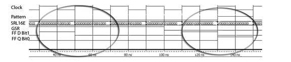
Figure
4 Failure mechanism shown
in (high or low) is being shifted into the SRL16E and
the bits within the
SRL16E are being shifted
out. When the GSR is released, the bits
remaining in the SRL16E will be shifted into the FDE properly
with the
output of the FDE feeding the input of the SRL16E. But by this time,
the pattern has been compromised and only a single ‘1’
remains in the
circular FIFO. Figure
5 shows where the missing pulses belong. A
different clock rate would produce different, interesting
patterns.
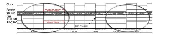
Figure
5 Missing pulse shown before GSR
Resolving the problem
The first thoughts toward
resolving the problem was to utilize an
enable signal on the SRL16E that is generated either
external to the
FPGA or
from internal timing. By holding the SRL16E in a disabled
state during the GSR, proper operation can be
obtained.
Figure
6 External/internal enable provided to the SRL16E
Figure 6 shows the proper operation if an enable is
applied. The issues
with this solution is “when is GSR inactive” and how is a
reset handled
during operation.
Tying the SRL16E enable to a reset function
resolves this issue but a more robust way would be to use the
GSR to
directly control the enable signal. GSR is an asynchronous signal
within the FPGA. As
such it should be double buffered to avoid
metastability issues. Code
Sample 2 shows an implementation doing
this.
library
ieee; use ieee.std_logic_1164.all;
library
unisim; use unisim.vcomponents.all;
entity
srl16e_bug is port (
clk
: in std_logic;
lsb_out
: out std_logic);
end entity
srl16e_bug;
architecture
rtl of srl16e_bug is
signal byte_internal : std_logic_vector(7
downto 0) := X"88";
signal after_gsr : std_logic_vector(1 downto 0) :=
"00";
-- synthesis translate_off
signal gsr_fake : std_logic;
-- synthesis translate_on
begin
-- synthesis translate_off
roc_i : roc -- Reset On Configuration.
generic map (width => 100 ns)
port map (O => gsr_fake);
-- synthesis translate_on
shift_right : process begin
wait until rising_edge(clk);
--
-- synthesis translate_off
if gsr_fake = '0' then
-- synthesis translate_on
after_gsr <= after_gsr(0) & '1';
-- Happens after the real GSR.
-- synthesis translate_off
end if;
-- synthesis translate_on
--
if after_gsr = "11" then --
Rotate right.
byte_internal <= byte_internal(0)
& byte_internal(7 downto 1);
end if;
end process shift_right;
lsb_out <= byte_internal(0);
end
architecture rtl;
Code
Sample 2 GSR Used as Enable
Both simulation and synthesis
constructs are included in the code
segment. The roc
primitive is a Xilinx Unisim to simulate a GSR
function. It is not
synthesizable. The signal gsr_fake
provides the
simulation equivalent of the GSR. The line
after_gsr
<= after_gsr(0) & ‘1’;
provides a signal that can only occur after GSR has terminated
since it
is based on FD devices that are held in reset by GSR.
The technology view is show
below.
Figure
7 Technology View showing GSR Enable
As can be seen in Figure 8, this again results in proper operation of the
circular shift register but without relying on an enable that
is not
controlled and timed by GSR.
This will guarantee that the SRL16E is
not shifting data until GSR is released.
Figure
8 Simulation utilizing GSR for Enable
Conclusion
While SRL16E implementations
as a FIFO should have no issue with
the affects of GSR, fixed pattern generators (circular
buffers) must be
looked at during an active GSR. Any clock edge that is present during
the GSR could corrupt data within the shift
register. It would be
prudent to add an enable that would guarantee the SRL16E does
not
shift during the GSR active
state.
Ron Hakola 918.906.6952 ron@hakola.us
Johan Sandstrom 310.977.9435
johan@sandstrom.org
With contributions by John
Retta